What is a PCB?
This page will go through the basics of what a PCB actually is, along with definitions and examples of many of the terms used with PCBs. Design is looked at on our “PCB Design” page.
Some links that might be helpful
When do I need a PCB?
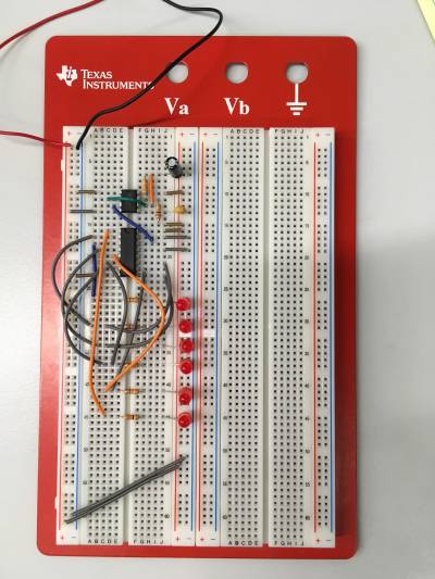
 Before fabricating a PCB, a circuit is often built using a breadboard or wire-wrapping technique to make sure that it works. While suitable for prototyping or proof-of-concept, breadboards and wire-wrapping methods should usually be avoided in final products, as they are prone to loose connections, misaligned pins, and other issues. Furthermore, properly designed PCBs can support electrical characteristics that other methods cannot.
If you don't have time to design and manufacture a PCB, you may want to consider using a perfboard. A perfboard is a rectangular sheet covered in a grid of through holes that can be used for soldering. Holes are connected by either running a wire between them or by making a solder bridge. Many also include pads on the side for surface mount components. Perfboards are more durable than breadboards and can save time when only one or two designs are needed. However, they are not recommended for circuits that are complicated or need to be replicated many times.
The rest of this article focuses on PCBs. If you are not sure which method for implementing your circuit design is best for your project, you can talk to a PI about the advantages and disadvantages of different methods. Keep in mind that for most projects, you will use multiple implementation methods as you develop your design.
What is a PCB?
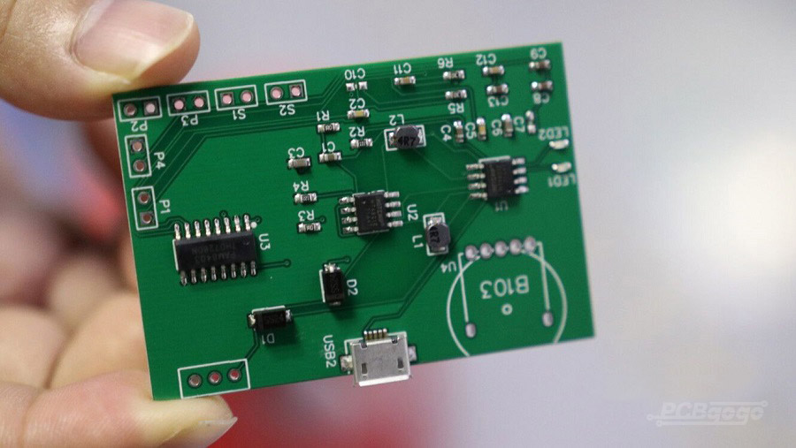
A PCB is a multi-layered substrate specially designed and fabricated for circuit designers to eliminate wiring and mechanically support their components. Let's step though that definition:
- Multi-layered substrate - A PCB starts as a sheet of layered material. This conmanly consists of a thin layer of copper on the bottom, a substrate called FR4 (FR5 is also common), and another thin layer of copper. You might have seem these sheets sitting below the Hive's milling machine (ProtoMat).
- Designed and fabricated - The first step in making a PCB is to design it using CAD (computer-aided design) software. Popular CAD tools include Eagle, Kicad, and Altera. The next step is to physically create the PCB, referred to as fabrication.
- Eliminate wiring - While the copper layers are electrically conductive, the FR4 is not. That means that by removing (etching away) copper, you leave behind a pattern that directs the flow of electricity. These copper connections (traces) electrically connect components exactly as wires do.
- Mechanically support - Unlike flexible wires, a rigid PCB can be used to connect (mount) components, such as resistors or chips. This is typically achieved through some form of soldering, in which a conductive metal “glue” to attach components to the PCB.
Traces on different copper layers can be connected by adding vias, which are holes drilled into the board and filled with a conductive metal, often copper. The process is known as electroplating. Electroplating covers every exposed inch of a surface in a thin layer of copper. This means that via drilling and electroplating should be done before etching traces. At the Hive, the electroplating process takes two hours, regardless of board design. More complex stackups (that is, the layering design of the PCB) can include more than two copper layers, different insulating materials, and more. Many PCBs you will come across are covered in a resin-based material, which is often green. This is called soldermask, and it can be added to isolate traces beyond just etching. You may also notice the presence of text and images, which is added using a silkscreen.
«Image of a PCB» «Labeled image of a PCB> «Stack up of a 2 layer board»
How do I make a PCB?
Making a PCB is done in three overarching steps: design, fabrication, and assembly.
- Design: Typically, one starts by developing a circuit, which may include simulations and/or prototyping on breadboard. The design of the board itself is then done on the computer using electronic computer-aided design (e-CAD) programs, such as KiCAD, EAGLE, or Altium, though there are many others.
- Fabrication: There are a number of different steps, depending on the complexity of your design, but a standard 2-layer board without vias begins by drilling any necessary holes, followed by etching/isolating the traces and components, and finally routing/cutting the board out. Soldermask and silkscreen can be applied after the board has been fabricated. See “The Official Fabrication Guide” page for step-by-step details.
- Assembly: the process of actually adding the components to the fabricated PCB. At The Hive, we have soldering stations to facilitate this, as well as solder paste and a reflow oven if you'd prefer. We can also make solder paste stencils.
Glossary
Substrate - the material between the two copper layers, FR4 is common
CAD - computer aided design; refers to any software used for design (SolidWords, EAGLE, CST Studio, etc.)
Etch - selectively removing copper to leave behind a conductive pathway in a specific shape
Isolate - electrically separating (isolating) two areas of copper, usually by etching
Trace - the copper path left behind after etching; traces function like wires
Soldering - a technique used to create conductive connections between two components, usually in a circuit
Via - a small, copper-filled hole drilled through a PCB which connects two or more layers
Electroplating - a chemical process that covers every exposed area of a PCB with a thin layer of copper
Stackup - a layered PCB design
Soldermask - an insulating resin applied to protect the PCB and further isolate traces; often green colored
Silkscreen - text printed on top of a soldermask to provide information about a PCB; often white colored
Pitch - the distance between the centers of two features, often the distance between the centers of two holes
Drill hit - another name for a drill hole
Mil - one-thousandth of an inch, a common imperial unit for small-scale designs
Route - a cutting process that removes the fabricated PCB from the rest of the substrate
