This is an old revision of the document!
Knowledge Base: PROTOMAT
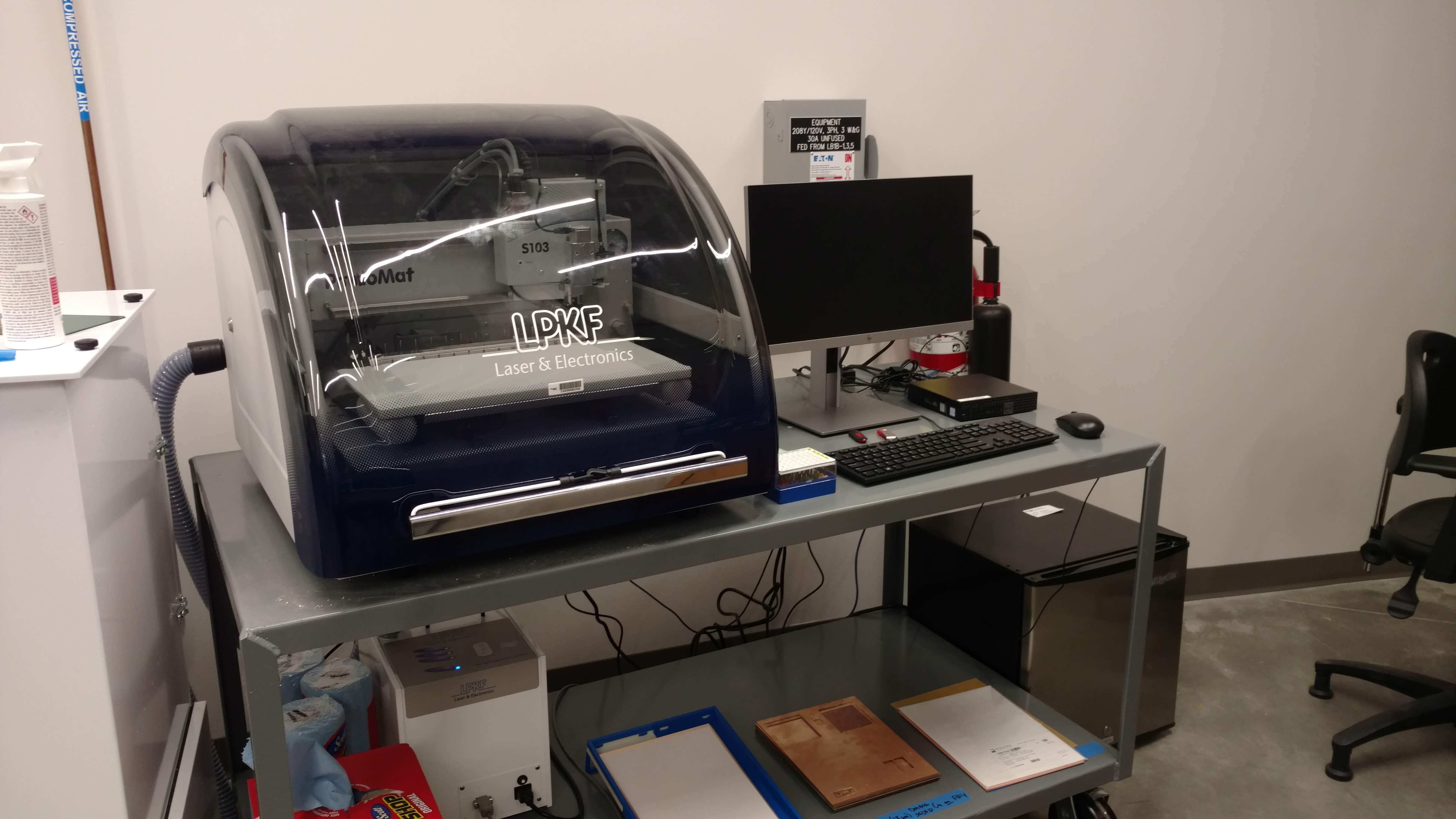
Table of Contents
- Overview
- Q&A
- Common processing errors
- Software cannot/did not connect to the tool
- My gerber/drill file didn’t show up on the CAM view.
- The tool didn't drill out my holes!
- The tool exchange was botched!
- The drill hits are incorrect, or the routing path was wrong!
- I can't change the layer/template option in the Import step!
Overview
The LPKF ProtoMat S103 is a 2.5-D CNC mill capable of drilling, milling, and routing to manufacture printed circuit board (PCB) and 2.5D structures on a variety of substrates. The tool is located in the Semi-Clean Room on the 1st floor of the IDC. It is part of the IDC’s PCB fabrication process flow. The tool uses a moving tray and toolhead that allow autonomous movement across the work space with a tool exchange methodology that allows for different mechanical processes to be carried out without user intervention, and a highly-accurate alignment algorithm that enables multi-machine fabrication processes.
Substrates:
- Fiberglass-based or carbon fiber reinforced polymers, including FR4
- The Hive provides 0.5 oz and 1 oz double-sided copper on 1.55mm FR4.
- PTFE or ceramic-filled base material
- Wood
- Nonferrous materials, such as aluminum or brass
- Plastics such as polyoxymethylen (“Delrin”), or ABS-Copolymere
Tool sizes
- Drill bits between 0.15mm and 3mm
- Contour routing, 1mm or 2mm
- Milling bits between 0.8mm and 3mm
- “Universal” cutting bits, 0.1 or 0.2mm
More details regarding tool structure or usage can be found in the following documents:
The Manual: ProtoMat S-series Manual.pdf
LPKF's “How-To” guides for some ProtoMat processes, including DXF import, stencils, and pocket milling: How to do things with the S103 (GDrive folder)
The ProtoMat software (“CircuitPro”) compendium: CircuitPro 2.3 Compendium.pdf
The vacuum system manual: Dust Extraction Manual Jet Stream iSeries-e-1-0.pdf
Our standard operating procedures: ProtoMat S103 SOP
Q & A
- How do I use the 0.15mm drill bit?
Our standard process easily handles drill hits down to 0.2mm (7.5 mil), but we have the capability to make 0.15mm (5.6 mil) drill hits as well with slightly more effort. See our 0.15mm Drill Hits page for details on that.
Common processing errors
- Software cannot/did not connect to the tool
First, make sure the ProtoMat hardware is on; if it's on already, there will be a red light under the toolhead (for the camera), and the status light on the toolhead should be at least blinking green. If it's not on, turn it on by toggling the green switch located underneath the cover, to the right of the working table, above the main power cable. Once you've confirmed the hardware is on, in the software, in the main toolbar (with the File menu), click “Machining” > “Connect”. Make sure that “S103” is selected in the dropdown menu and click “Connect”. Let the connection process happen, and then try the fabrication again.
- My gerber/drill file didn’t show up on the CAM view.
You probably forgot to assign it a layer. If this happens, the software will put the gerbers onto their own layers that are named with the gerber's name. Try re-importing the files, and make sure you’ve assigned each file a Layer/Template (see figure 11). Also make sure to delete the incorrectly-generated layers (right-click and select “Delete”).
- The tool didn't drill out my holes!
You likely forgot to import the drill file. You'll have to restart the project over again. Sorry.
- The tool exchange was botched!
Stop the process as soon as possible, if it's still running. Go get a PI. If they don't know what to do, ask them to message our Slack channel.
- The drill hits are incorrect, or the routing path was wrong!
There are a couple of possible reasons for this.
- You may not have imported the drill file or the board outline gerber correctly.
- The bits in the magazine may have been incorrect.
- The tool may have done something silly.
In any of these cases, there is no good solution other than to restart the project and double check all of these (if possible) before starting to re-process. Sorry.
- I can't change the layer/template option in the Import step!
Sometimes, for reasons unclear, a Gerber file gets automatically assigned to a undesired layer in the LPKF software on the ProtoMat, and cannot be changed. If this happens, what you need to do is highlight all the polygons on that layer in question that were imported, and move them to the correct layer (right click > Move to Layer). Highlighting a whole layer requires playing with the Layers pane on the left, and then click-and-drag across all the polygons. If there are things on that layer that are supposed to be there (e.g. you need to move only some of the polygons off the TopLayer layer), it can be worth just starting the process again, and importing the messed up Gerber first.
Details of this process can be found in this short video.